
When to Use True Position in Design Thinking: A Guide to Effective Application

Update:
April 1, 2026
6 min read
when to use true position in design thinking

In the world of design thinking, precision plays a crucial role in ensuring that products not only meet functional requirements but also deliver a seamless user experience. One of the most important concepts when dealing with geometric design and tolerancing is True Position. Understanding when and how to use true position in design thinking can significantly enhance the effectiveness of your design process and improve product quality. In this guide, we’ll dive into the concept of true position, explain when it’s necessary to apply it, and offer practical tips for its integration into your workflow.

What is True Position?
true position in design thinking

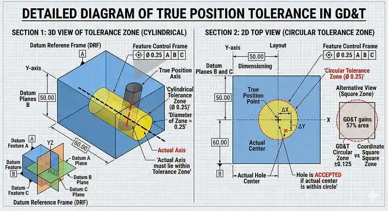
True position is a term used in Geometric Dimensioning and Tolerancing (GD&T) to define the exact, theoretically perfect location of a feature, such as a hole, slot, or pin, relative to a reference point known as a datum. Unlike simple dimensional tolerances, which only define the allowable variation in size, true position defines the location of a feature within a tolerance zone, often circular or cylindrical. This ensures that parts fit together as intended, even if they have slight variations in size or shape.

True position is critical in ensuring that multiple features align properly in an assembly, particularly in situations where precise interaction between components is required.

When to Use True Position in Design Thinking

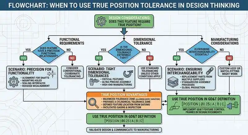
Understanding when to use true position is essential in design thinking. Here are some scenarios where this concept is vital:

1. When Precision is Crucial for Functionality

In designs where precise alignment of components is essential for functionality, true position becomes a key factor. For instance, when multiple holes need to align in an assembly, true position ensures that each hole is placed within an acceptable tolerance zone. This helps to avoid misalignment, which could otherwise lead to product failure or operational issues.

2. When Multiple Features Must Interact

For complex assemblies, such as automotive or aerospace components, multiple features often need to fit together seamlessly. True position allows you to specify not only the location but also the orientation of features relative to each other. This is crucial when parts from different manufacturers or production batches need to be assembled together without gaps or misalignments.

3. When Dealing with Tight Dimensional Tolerances

True position is particularly effective when there are tight dimensional tolerance requirements. It enables you to control the location of features with high precision, making sure the components fit properly even when size variations occur. This is especially important in industries where tight tolerances are a part of daily operations, such as the automotive, medical device, and aerospace sectors.

4. When Flexibility in Manufacturing is Needed

In high-volume production, true position offers flexibility without compromising accuracy. By utilizing Maximum Material Condition (MMC) or Least Material Condition (LMC) modifiers, designers can allow more tolerance when features are produced at their least material condition. This ensures that parts can still be manufactured within acceptable limits while providing flexibility for variation during production.

5. When Ensuring Interchangeability

True position guarantees that parts from different production runs or suppliers will fit together properly. This is essential in mass production, where parts must be interchangeable despite potential variations in the manufacturing process. Using true position helps to standardize feature locations, ensuring that parts will fit together correctly, improving the efficiency of assembly processes and reducing the chances of defects.

Integrating True Position into Your Design Workflow

To effectively integrate true position into your design thinking process, it’s important to follow best practices that help ensure accuracy and consistency across your designs. Here are some actionable tips:

1. Establish Clear Datums

Begin by defining reliable datums early in your design process. Datums serve as reference points for all features, ensuring consistency in feature location and orientation. A well-chosen datum system simplifies your true position application, making it easier for downstream teams to interpret and implement tolerances.

2. Define Tolerance Zones Thoughtfully

When specifying true position, it’s essential to consider how the tolerance zone reflects the functional needs of the part. Whether you’re designing a small component or a complex assembly, ensure that your tolerance zones reflect real-world use rather than theoretical ideals. This approach will result in more practical and manufacturable designs.

3. Leverage Material Condition Modifiers

Use MMC or LMC where appropriate to provide bonus tolerance. This allows for more flexibility in manufacturing while maintaining the desired fit and function. It’s particularly useful when designing for mass production, where small variations in material size are inevitable.

4. Use Control Frames and Basic Dimensions Clearly

Document your designs with clear control frames and basic dimensions to reduce ambiguity. This ensures that engineers, manufacturers, and quality control teams can easily interpret the design intent and apply the necessary tolerances correctly.

5. Validate Assumptions Through Prototyping

Before finalizing your design, validate your positional tolerance assumptions through prototyping or simulation. This helps to identify whether your tolerance zone is appropriate and whether the features will interact as intended during assembly.

6. Communicate Effectively Across Teams

Ensure that everyone involved in the design, manufacturing, and inspection processes understands the role of true position. Clear communication will minimize errors and misinterpretations, leading to smoother collaboration and more accurate results.

Why True Position Matters for Design Accuracy

True position is not just a technical specification—it’s a tool that ensures the accuracy and reliability of your designs. By accurately defining the location and orientation of features, true position reduces ambiguity and ensures that parts fit together as intended, even under varying manufacturing conditions. This is essential for delivering products that meet user needs and function as expected.

By integrating true position into your design thinking process, you ensure that your designs are both creative and technically sound. The balance between creativity and precision is what sets your work apart and enables you to deliver high-quality products consistently.

Final Thoughts

True position is a fundamental concept that every designer working with precision components should understand. By applying this concept strategically, you can ensure that your designs meet functional, manufacturing, and user requirements. Whether you’re designing a simple mechanical part or a complex product with many interacting features, true position allows you to control location and orientation with unparalleled precision.

To sum up, true position is not just for experts in geometric dimensioning and tolerancing (GD&T); it’s a versatile tool for anyone involved in the design and production of precise, reliable products. By understanding when to use true position in design thinking, you can create designs that are both innovative and manufacturable, helping to bring your ideas to life with accuracy and efficiency.


Frequently Asked Questions

What are the 4 D's of design thinking?

The 4 D’s of Design Thinking are crucial steps within the Double Diamond framework that guide the creative problem-solving process. Here’s a breakdown of each stage:

  1. Discover:
    • The first stage focuses on exploring and understanding the problem. In this phase, designers gather insights through research, observation, interviews, surveys, and user testing. The aim is to identify the needs, challenges, and opportunities that the users face. The goal is to uncover as much information as possible to inform the design process.
  2. Define:
    • After gathering insights in the Discover phase, the Define stage aims to synthesize the findings into a clear, concise problem statement or design brief. This stage helps to focus on the most critical issues to solve and creates a clear direction for the next phases. It involves organizing data, identifying patterns, and reframing the challenge into an actionable goal that aligns with user needs.
  3. Develop:
    • In this phase, the focus shifts to generating ideas and exploring solutions. Using brainstorming, prototyping, and testing, designers experiment with different concepts and approaches. The goal is to iterate and refine ideas, collaborating across teams to create innovative solutions that address the problem defined in the previous stage.
  4. Deliver:
    • The final stage is about bringing the solution to life. This involves refining the prototype, finalizing the design, and launching the product or solution. During this phase, designers work on production, scaling, and implementing the solution in real-world contexts. Testing, feedback, and further iteration are part of this process to ensure the solution meets user needs and solves the problem effectively.

In the Double Diamond framework, these stages are divided into two diamonds:

  • The first diamond (Discover and Define) emphasizes divergent thinking (expanding possibilities and exploring various solutions) and convergent thinking (narrowing down to focus on the most important aspects).
  • The second diamond (Develop and Deliver) similarly emphasizes diverging through ideation and converging toward the final product.

This approach ensures a thorough exploration of problems and solutions, promoting creativity while maintaining a user-centered focus.

The true position is a concept in geometric dimensioning and tolerancing (GD&T) that defines the exact location of a feature, such as a hole, relative to a reference point or datum. It is a way to control the location of a feature to ensure that it is manufactured within specified limits, allowing for correct assembly and function.

For example, when working with a hole, the true position is typically set at the center of the hole’s axis. This axis represents the ideal or perfect location of the hole, and any deviation from this ideal position is controlled using a tolerance zone. The tolerance zone can be 2D or 3D and is defined by a diameter around the true position. This zone specifies the permissible area in which the center of the hole can vary, ensuring that the hole is positioned correctly within the allowed limits.

For instance, if the true position of a hole is specified with a tolerance of ±0.2mm in a 2D plane, the center of the hole can move within a 0.2mm radius from the true position, but it must stay within that defined zone. The true position helps ensure that even with slight variations during manufacturing, the hole remains in the correct location for proper assembly with other components.

The 3-2-1 rule in Geometric Dimensioning and Tolerancing (GD&T) is a system used to establish a reference framework or a datum system for locating and orienting a part during manufacturing and assembly. It defines how a part or feature should be positioned and supported in three-dimensional space using contact points on the part. Here’s a detailed breakdown:

3-2-1 Rule Explanation:

The rule specifies the number of contact points required to establish the primary, secondary, and tertiary datums that will define the part’s position in space.

  1. Primary Datum (3 points):
    • The primary datum is the first reference used to locate the part and is typically the most functionally important feature. This feature is often the face or surface that mates with other components in an assembly.
    • 3 points of contact are required to define the primary datum. These points provide stability in the part’s orientation and prevent movement in 3D space (X, Y, and Z axes).
    • The primary datum usually controls the part’s orientation (e.g., aligning a flat surface or a hole to ensure the part fits into the assembly correctly).
  2. Secondary Datum (2 points):
    • Once the primary datum is defined, the secondary datum further refines the part’s position and defines the orientation relative to the primary datum.
    • 2 points of contact are required for the secondary datum. This typically involves a line or edge that helps align the part with respect to the primary datum. For example, a side face or a hole can be used to define this secondary datum.
    • The secondary datum helps with the part’s location in one additional direction, often ensuring that the part is positioned in the plane perpendicular to the primary datum.
  3. Tertiary Datum (1 point):
    • Finally, the tertiary datum is used to control the part’s location and orientation in the third direction.
    • 1 point of contact is required to define the tertiary datum. This contact point ensures that the part is secured along the final axis (often the vertical axis, depending on the primary and secondary datums).
    • The tertiary datum is generally the last point of support that completes the part’s three-dimensional location.

How It Works in Practice:

The 3-2-1 rule ensures the part is located and oriented accurately on all three axes:

  • 3 points on the primary datum fix the part’s orientation and prevent rotation in the X, Y, and Z axes.
  • 2 points on the secondary datum refine the part’s positioning and control its orientation relative to the primary datum.
  • 1 point on the tertiary datum ensures that the part is fixed along the final axis and prevents further movement.

Example:

Consider a metal plate that must be positioned and aligned in a machine for a manufacturing process:

  • The primary datum could be a flat face of the plate, where 3 points (such as 3 support pins) would be used to define the part’s orientation.
  • The secondary datum might be a hole or an edge of the plate, where 2 points (such as 2 support pins) help further position the plate along the second axis.
  • The tertiary datum could be a corner or another edge of the plate, where 1 support point (such as a pin) helps define the final position of the plate in the third direction.

Key Takeaways:

  • The 3-2-1 rule is crucial for defining a precise, reproducible positioning system for parts in manufacturing.
  • Primary, secondary, and tertiary datums help ensure parts are oriented and located properly for assembly or other processes.
  • The system prevents parts from shifting or rotating during handling, inspection, or assembly, ensuring consistent quality and functionality.

This rule is fundamental for parts that need to be precisely located and oriented in 3D space for successful manufacturing and assembly processes.

The true position in Geometric Dimensioning and Tolerancing (GD&T) is indeed a diametrical call-out, not a radius. The true position defines the exact location of a feature, such as a hole or slot, relative to a datum system and is typically expressed as a diameter. Here’s a more detailed explanation of this concept:

True Position: Diameter vs. Radius

  • The true position tolerance zone is typically defined using a diameter because the tolerance zone represents the area in which the center of a feature (like a hole) is allowed to vary. The diameter is used to define the width of this tolerance zone.
  • Radius is half the diameter, so when working with true position, it’s crucial to double the radius value to get the diameter. For example, if the true position tolerance is given as ±0.2mm with a radius, you would need to double that radius to express the total allowable diameter of the tolerance zone, which would be 0.4mm in total.

True Position Gauge

  • When creating a true position gauge (a tool used to inspect or measure the position of a feature against the true position tolerance), you essentially need to determine the tolerance zone.
  • If you are given a minimum allowed diameter for a hole’s true position (for example, if the true position tolerance is ±0.3mm from the nominal position), the gauge can be created by subtracting the amount of true position tolerance from the minimum allowed diameter.
  • For example:
    • If the nominal hole size is 10mm and the true position tolerance is ±0.3mm, the gauge diameter will be:
      • Minimum allowed diameter = 10mm
      • Subtracting the true position tolerance (±0.3mm), you get the final gauge pin diameter of 9.4mm (because the true position allows the center of the hole to shift by up to 0.3mm in any direction).

Casual Explanation:

  • To make a true position gauge to check the location of a hole, you would take the minimum allowed diameter of the hole and subtract the true position tolerance (expressed as a diameter) to determine the pin diameter that will fit into the hole. This ensures that the hole is within the correct tolerance zone defined by the true position call-out.

In Summary:

  • The true position is diametrical, meaning it refers to a diameter tolerance zone rather than a radius.
  • When converting from radius to diameter for true position, double the radius value to get the equivalent diameter tolerance zone.
  • For a true position gauge, subtract the true position tolerance from the minimum allowed diameter to determine the correct pin size for checking the hole’s location.

This method ensures that the hole or feature is within the specified location tolerance, ensuring proper fit and function in assembly.

user 1
Author

With over 5 years of experience in web development, I create visually appealing, user-friendly websites optimized for performance and SEO. Specializing in UI/UX design, front-end development, and WordPress, I deliver custom solutions that align with your brand’s goals, ensuring a seamless online experience that drives engagement and growth. Let’s collaborate to bring your vision to life with a website that works for you.

Share On

Interested working wIth me ?